Grundfos Inverter Setup
This document explains how to configure a Grundfos RSI0100 inverter so that it can be remotely logged and controlled over Modbus RTU through the Yeti Gateway.
Follow the steps in order
Do not skip any step. Each step depends on the one before it — for example, the Modbus parameters are hidden until the Advanced Level password is set, and Remote Control will not take effect until the Modbus wiring and parameters are correct.
Prerequisites
- A Yeti Gateway device
- A Grundfos RSI0100 inverter with an RS-485 Modbus interface
- Access to the inverter's local control panel
- A 13 V power source for the Yeti Device
Part 1: Wiring
The Yeti Device exposes 4 wires:
| Wire | Purpose |
|---|---|
| Red / Black | Power (13 V) |
| Orange (A) | Modbus A |
| White (B) | Modbus B |
Connect the Modbus wires from the Yeti Device to the Grundfos inverter's RS-485 terminals:
- Orange A → Grundfos A
- White B → Grundfos B
Note
As with any RS-485 Modbus wiring, A must always connect to A and B must always connect to B. Reversing them will prevent communication.
Part 2: Unlock Advanced Settings
The Modbus parameters are only visible under the Advanced Level menu, so this password must be set first.
| Step | Image |
|---|---|
| 1. Press the Main Menu | 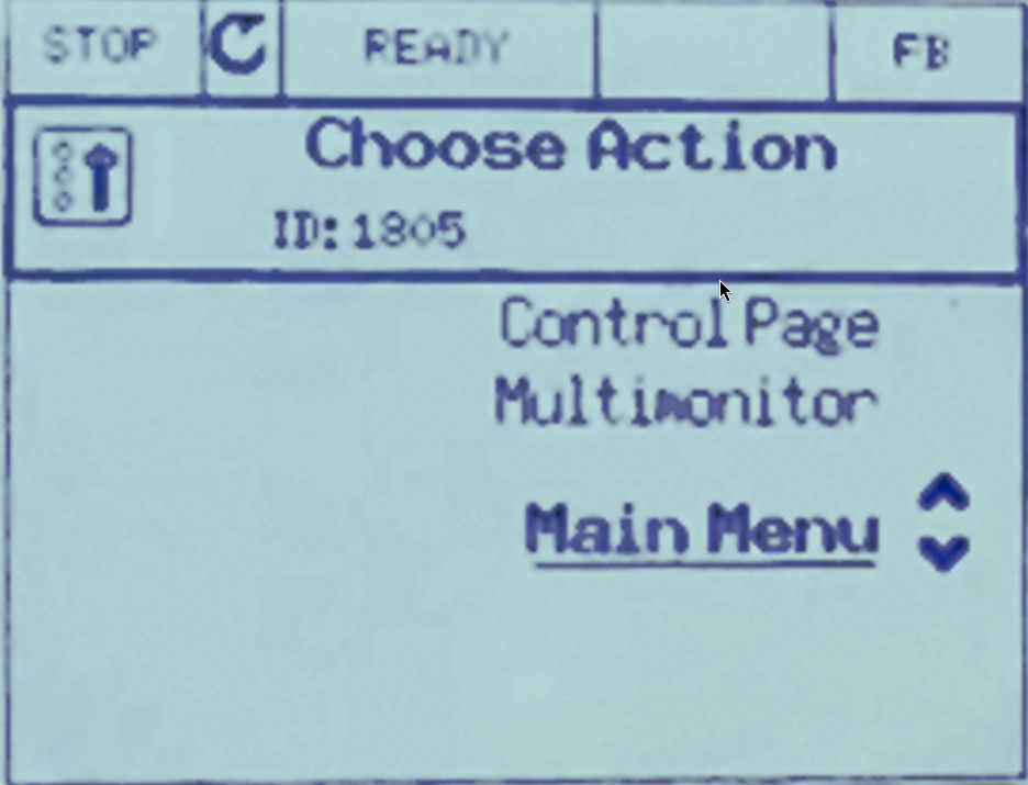 |
| 2. Press the Quick Setup | 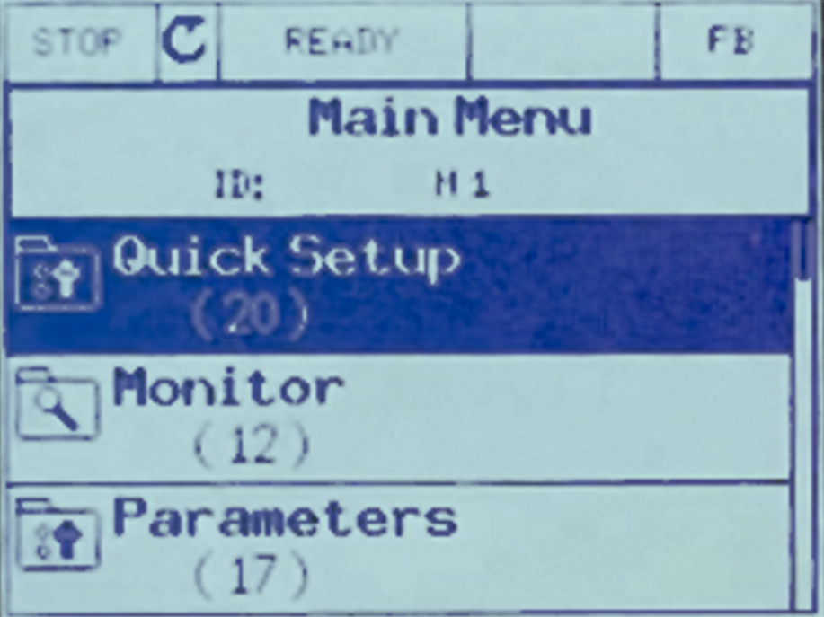 |
| 3. Press the Advanced Level PW and set it to 681400 | 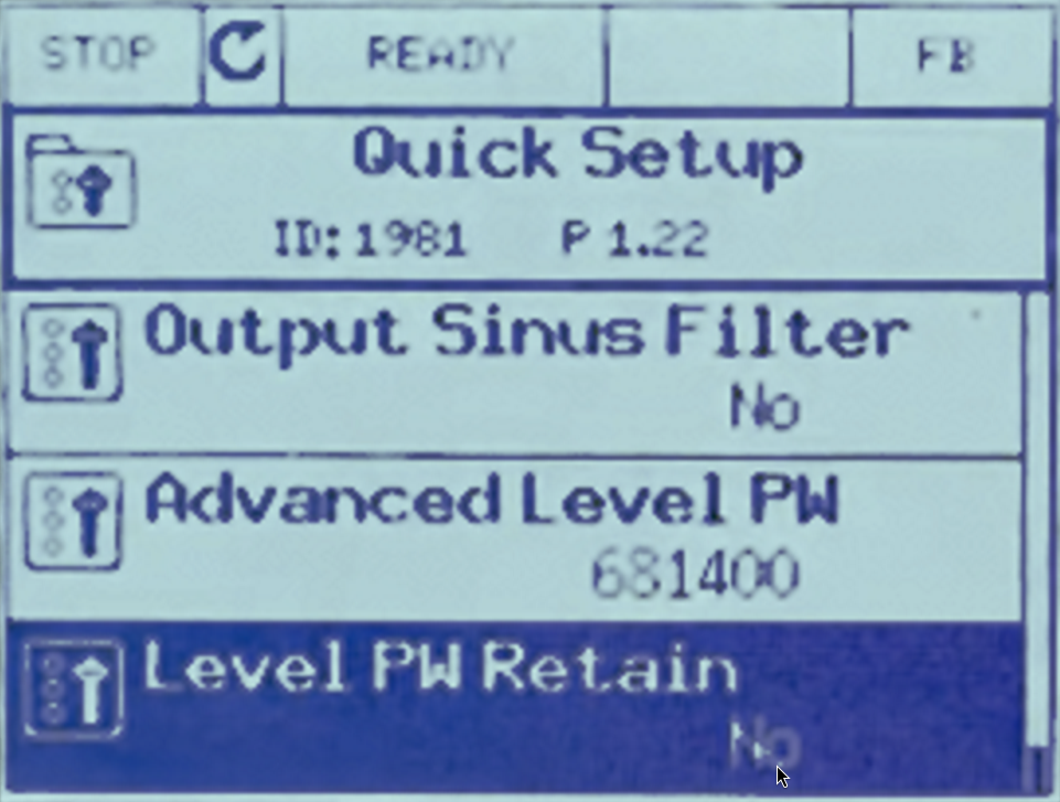 |
Part 3: Configure Modbus Parameters
| Step | Image |
|---|---|
| 1. Go to Main Menu. | |
| 2. Go to I/O and Hardware. | 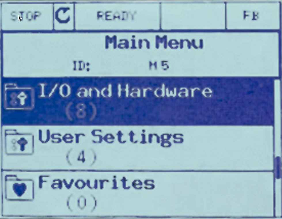 |
| 3. Go to RS-485. | 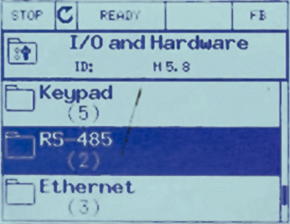 |
| 4. Go to Common settings: | 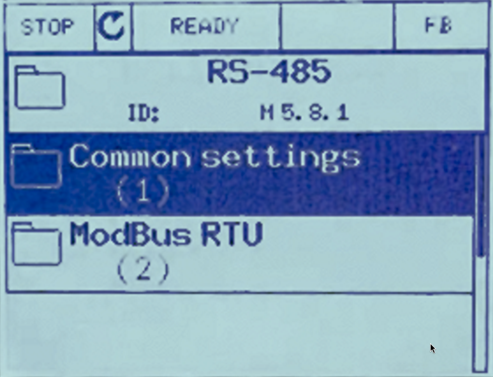 |
5 Set Protocol to ModBus RTU. |
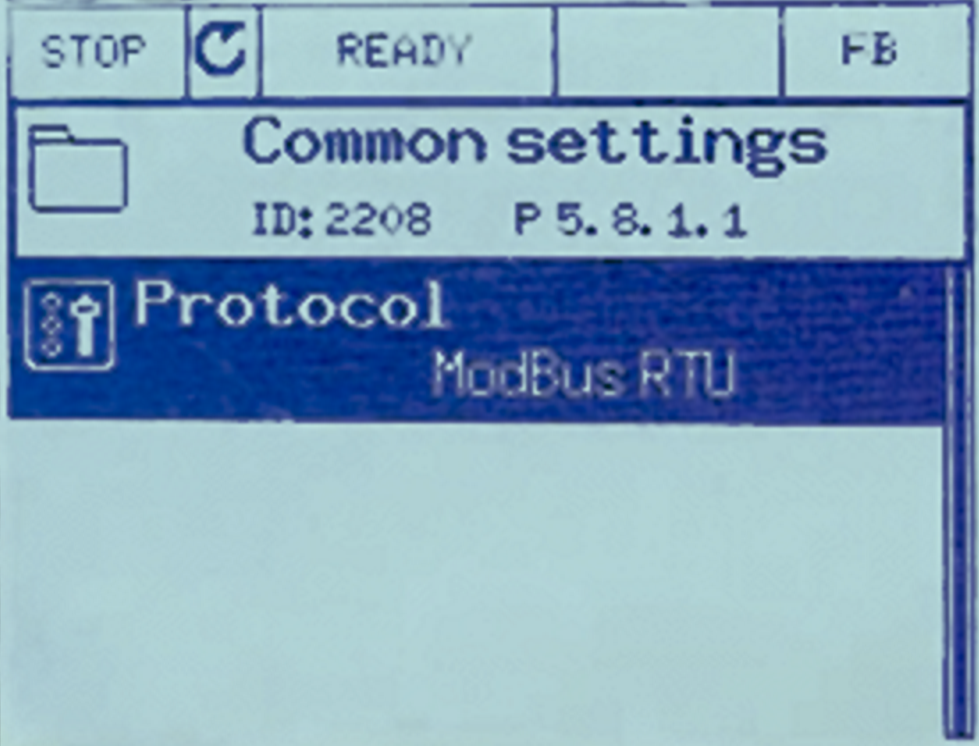 |
| 6. Go back to the RS-485 page. | |
| 7. Go to Modbus RTU → Parameters and set: | 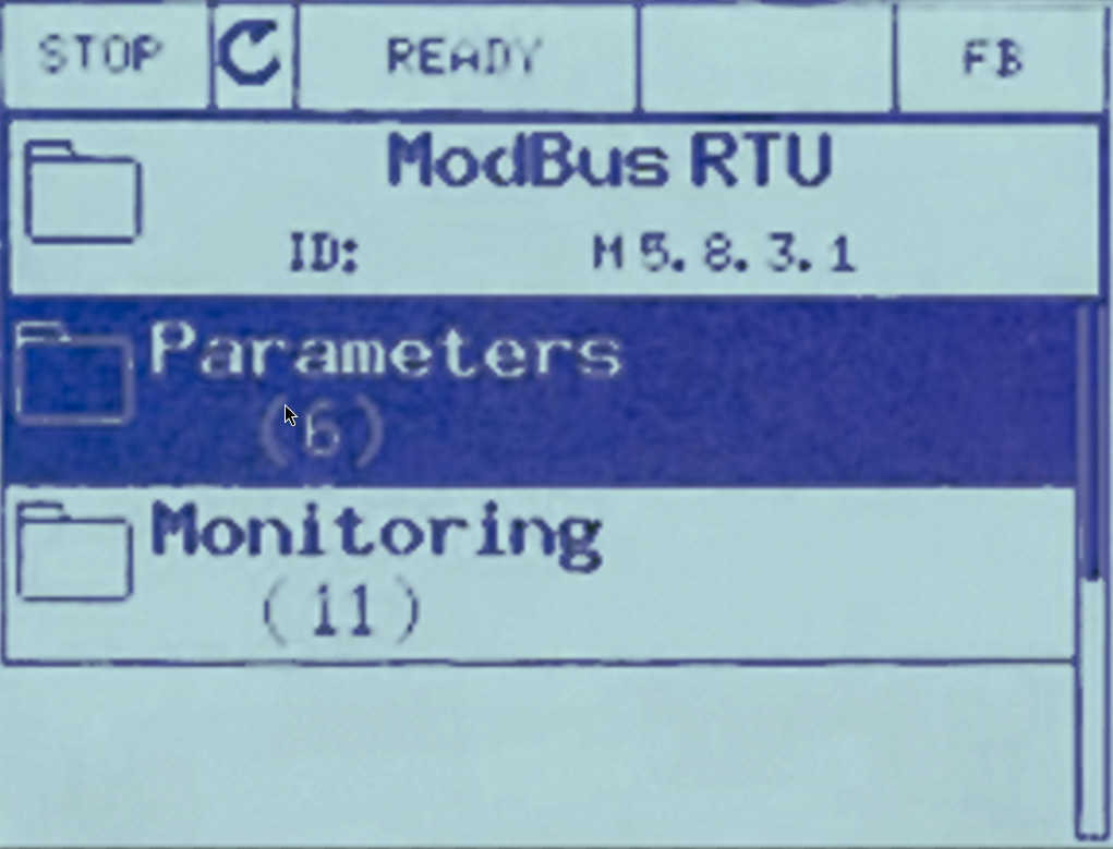 |
    | Parameter     | Value |
    | ------------- | ----- |
    | Slave ID      | 1     |
    | Baud Rate     | 9600  |
    | Parity Type   | None  |
    | Stopbits      | 1     |
    | Comm. Timeout | 10 s  |
    | Operate Mode  | Slave |
Part 4: Enable Remote Control
This step hands control of Start/Stop over to the fieldbus (Modbus) connection, which is what allows the Yeti Gateway to control the pump remotely.
| Step | Image |
|---|---|
| 1. Go to Main Menu. | |
| 2. Go to Parameters. | 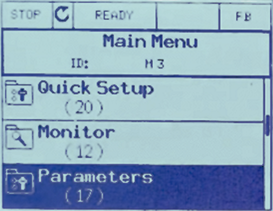 |
| 3. Go to Start/Stop Setup. | 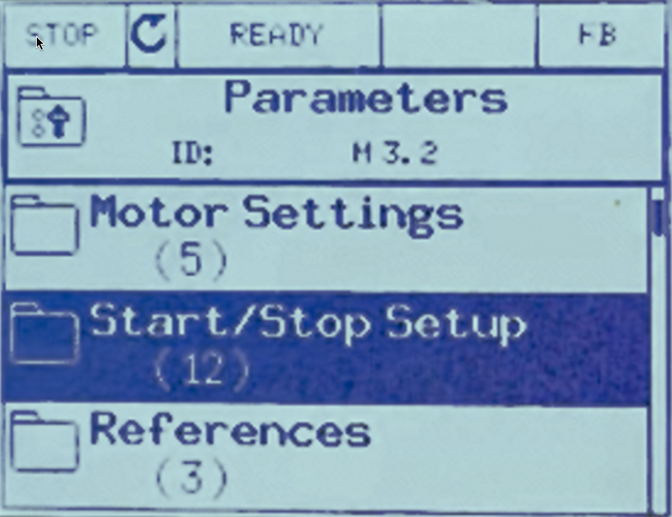 |
4. Set Rem Control Place to FieldbusCTRL. |
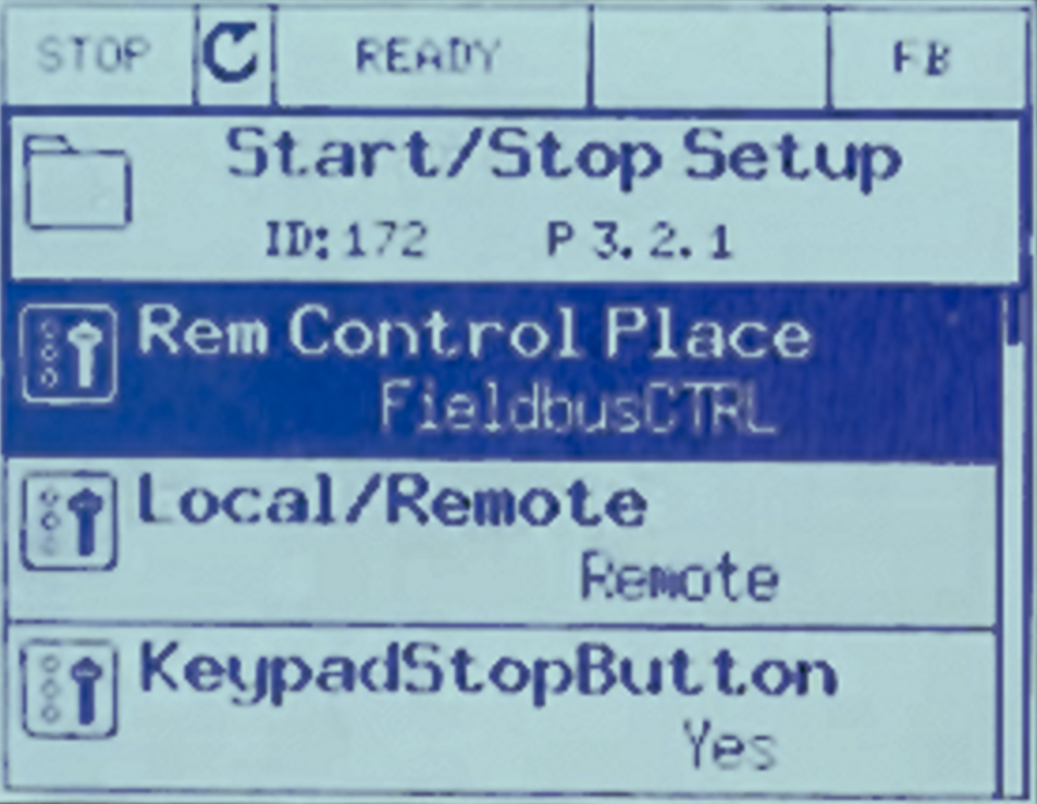 |
Part 5: Add the Device on the Yeti Gateway
Once the inverter is wired and configured as above, add it as a Modbus device on the Yeti Gateway so it can log and control the pump:
- Follow Part 4: Modbus Configuration in the Device Setup guide to add a new device using:
- Slave ID:
1 - RTU settings matching Part 3 above (
9600baud,Noneparity,1stopbit)
- Slave ID:
- Add the registers you need to read/write, referring to the Grundfos Modbus register list for the RSI0100 (e.g. run/stop, setpoint, status, actual value registers).
- Save the Modbus settings and restart the gateway to apply the configuration.
Once saved, the pump's telemetry will appear on the Application Server dashboard, and Start/Stop/setpoint commands sent from the Yeti Gateway will now be honored by the inverter.